banner
Products
Home /

YOKOGAWA

/Yokogawa AAI835-S00 S2 Analog I/O Module
Yokogawa AAI835-S00 S2 Analog I/O Module

Yokogawa AAI835-S00 S2 Analog I/O Module

PRODUCT REFERENCE VERIFICATION

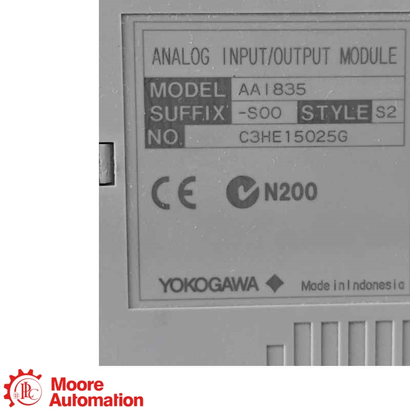
AAI835-S00 S2

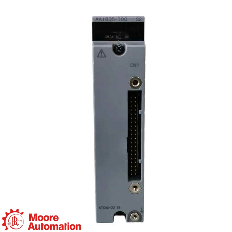
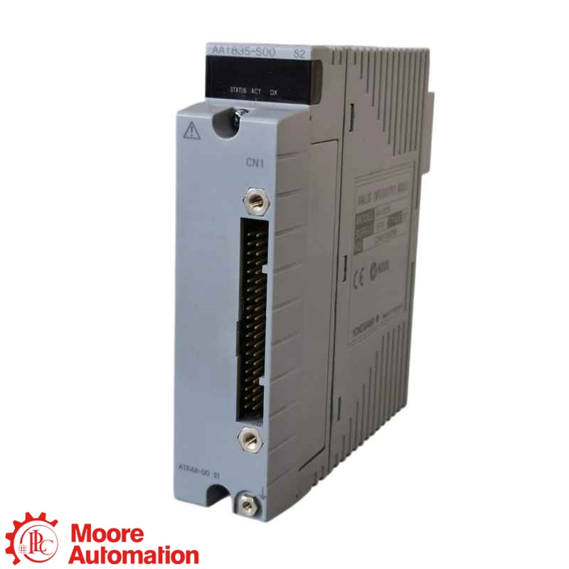
The AAI835-S00 S2 is a Yokogawa current analog I/O module for compatible field control stations. It combines four isolated 4–20 mA input channels and four isolated 4–20 mA output channels, 10 ms data updating, field-to-system and channel-to-channel isolation, and support for dual-redundant configuration.

CATALOGAAI835-S00 S2
SIGNAL4–20 mA
CHANNELS4 AI + 4 AO · isolated
STYLES2 verification required
BRANDYokogawa
PRODUCT TYPEAnalog I/O Module
CONDITION / WARRANTYOriginal New · One-Year Warranty
VERIFICATIONConfirm suffix, style and terminal hardware
REQUEST A QUOTE
  • Brand :

    Yokogawa
  • Part Number :

    AAI835-S00 S2
  • Description :

    Analog I/O Module
MODEL SEARCHFind a specific part numberOpen the best-matched Moore Automation product page directly.
PRODUCT INFORMATION● OFFICIAL YOKOGAWA REFERENCE
PRODUCT REFERENCE VERIFICATION

AAI835-S00 S2

ANALOG I/O CONFIGURATION

4–20 mA · 4 INPUTS + 4 OUTPUTS · ISOLATED CHANNELS

PRODUCT ROLE
AAI835-S00 S2 is a Yokogawa current analog I/O module for compatible field control stations. It receives four isolated 4–20 mA inputs and sends four isolated 4–20 mA outputs, with field-to-system and channel-to-channel isolation, 10 ms data updating and support for dual-redundant configuration.
INSTALLATION CHECK
Confirm the complete AAI835-S00 S2 nameplate, -S standard-function suffix, S2 style, node or FCS release, redundancy arrangement, 4–20 mA channel assignments, terminal block or adapter, KS1 cable and field wiring before installation.
👩‍💼
WANT THE BEST PRICE?
Frida
Sales Leader 🏆
EMAILsales5@mooreplc.comWHATSAPP+86 153 5940 8275
ORDER NUMBER BREAKDOWN

How the AAI835-S00 S2 Reference Is Identified

AAI835
Model code4-channel input / 4-channel output 4–20 mA analog I/O module with isolated channels
-S
Function suffixStandard type. Yokogawa identifies -H separately for HART digital communication.
00
Order-code segmentConfirm the complete suffix on the installed nameplate; terminal hardware is ordered with separate option codes.
S2
Style identifierMatch the stated S2 style, node/FCS release and installed-system requirements before replacement.
OFFICIAL YOKOGAWA REFERENCE

Technical Specifications

VERIFY COMPLETE CONFIGURATION
AAI835 FAMILY

Engineering data at a glance

Click “+” to expand more specifications.

LENGTH10.75 cm
WIDTH3.28 cm
HEIGHT13 cm
WEIGHT0.3 kg
Product arrival inspection record.
Electrical Performance
Input resistance, power ON290 Ω at 20 mA to 450 Ω at 4 mA
Input resistance, power OFF500 kΩ or higher
Allowable output load0–750 Ω
Open-circuit detectionLess than 0.65 mA
Input accuracy±16 μA
Output accuracy±48 μA
Temperature drift±16 μA / 10 °C
Withstanding voltage500 V AC for 1 minute
At an applicable ER-bus node ambient of 60–70 °C, Yokogawa specifies an allowable output load of 200–750 Ω. Cable electrical characteristics can limit withstand voltage.
Power and Redundancy
Maximum current consumption360 mA at 5 V DC; 450 mA at 24 V DC
IsolationField-to-system and channel-to-channel
RedundancyDual-redundant configuration supported
Terminal and Cable Compatibility
Pressure-clamp terminalsATI3S single / ATI3D dual-redundant
Terminal-board pathATK4A + KS1 + AEA4D
Fixed 2-wire pathATB3A + KS1 + AEA3D
Pressure-clamp wire size0.5–2 mm²; with sleeve 0.5–1.5 mm²

For ATK4A + AEA4D, each input channel can be selected for powered 2-wire transmitter input or non-powered 4-wire transmitter/current input. With ATB3A + AEA3D, all input channels use powered 2-wire transmitter input. Confirm the installed terminal assembly and wiring diagram before replacement.

FAQ

AAI835-S00 S2 Function, Configuration and Replacement FAQ

What does AAI835-S00 S2 do?

AAI835-S00 S2 is a Yokogawa analog I/O module that exchanges 4–20 mA signals with a compatible field control station. Its configuration is four isolated analog inputs plus four isolated analog outputs, and it must be used only with matching Yokogawa node, terminal and wiring hardware.

How many channels does AAI835-S00 S2 provide?

AAI835-S00 S2 provides eight mixed analog channels: four 4–20 mA input channels and four 4–20 mA output channels, with isolated channels. It is not an eight-input-only or eight-output-only module, so the I/O allocation must match the configured control database.

Does AAI835-S00 S2 include HART communication?

AAI835-S00 S2 carries the -S standard-type suffix, while Yokogawa identifies -H variants for digital HART communication. Therefore HART capability must not be assumed for AAI835-S00 S2; confirm the full order code and project requirement before substitution.

Which terminal hardware can be used with AAI835-S00 S2?

AAI835-S00 S2 can be paired with supported Yokogawa isolated-analog terminal arrangements such as ATI3S or ATI3D, or with ATK4A/ATB3A adapter paths and the applicable KS cable and terminal board. The selected hardware determines transmitter wiring options, so the existing terminal assembly must be verified.

Where is AAI835-S00 S2 installed?

AAI835-S00 S2 is installed as field I/O in compatible Yokogawa ESB-bus node units or field control units. Compatibility depends on the exact node or FCS model, system release, slot assignment, terminal hardware and configured 4–20 mA channel database.

Can another AAI835 style replace AAI835-S00 S2 directly?

AAI835-S00 S2 should not be replaced solely by matching the AAI835 base code. The -S00 suffix, S2 style, firmware or system-release support, terminal block or adapter, redundancy arrangement and channel wiring must all match the installed configuration.

What must be checked before installing AAI835-S00 S2?

Before installing AAI835-S00 S2, confirm the complete nameplate, S2 style, compatible node or FCS, 4–20 mA input/output assignments, terminal block or adapter, KS cable, two-wire or four-wire transmitter arrangement, redundancy requirement, grounding and the saved control-system configuration.

CONTACT PRODUCT SPECIALIST

Check AAI835-S00 S2 configuration with Frida

Provide the complete AAI835-S00 S2 nameplate, node or field control unit, terminal hardware, channel wiring, system release, quantity and destination for compatibility checking.

CHOOSE A DIRECT CONTACT METHOD
DATA SHEET

Manuals and Official References for
AAI835-S00 S2

Official manufacturer-reference information for the Yokogawa AAI835-S00 S2 Analog I/O Module.

Official AAI835 datasheet

Yokogawa GS 33K50F60-50E documents the AAI835 electrical performance, 4-input/4-output isolated 4–20 mA configuration, 10 ms update period, accuracy, load, power, weight, dimensions, redundancy capability and model/suffix codes. GS 33J60A20-01EN documents the supported terminal blocks, adapters, KS cable and field wiring.

OPEN OFFICIAL DATASHEET ↗FIELD CONNECTION SPECIFICATION ↗

Contact to Get Support

Send the complete model, quantity, terminal hardware, system release and your technical or purchasing question.

Specifications above are from the official Yokogawa AAI835 documentation. Confirm the complete AAI835-S00 S2 nameplate, terminal option, S2 style and installed-system records before ordering or replacement.

YOKOGAWA FIELD I/O · ANALOG INPUT / OUTPUT

How AAI835-S00 S2 Fits a Yokogawa Field I/O System

Yokogawa is the brand; AAI835-S00 S2 is the mixed isolated analog I/O module; and its four 4–20 mA inputs plus four 4–20 mA outputs connect field transmitters and final control elements to a compatible field control station.

Yokogawa · BRAND
AAI835 Analog I/O Module4 AI · 4 AO · 4–20 mA · ISOLATED
SYSTEM ROLE

FIELD SIGNAL CONVERSION

Converts isolated 4–20 mA field inputs to controller data and controller data to isolated 4–20 mA outputs.
CHANNEL FIT

4 INPUTS · 4 OUTPUTS

The mixed channel allocation must match the configured FCS database and field-loop assignments.

CONNECTION DATA

TERMINAL OR KS CABLE

Use the documented ATI3S/ATI3D terminal path or supported adapter, KS cable and terminal-board combination.

System relationship: verify the full AAI835-S00 S2 reference, node or FCS model, style revision, terminal assembly, transmitter wiring method, channel database and system release before replacement.
VERIFICATION EVIDENCE

Evidence needed to verify AAI835-S00 S2 correctly

Product Identity

Match AAI835-S00 S2 to the complete Yokogawa nameplate, suffix, style and installed hardware record.

Installation Context

Document the node or FCS, slot, terminal block or adapter, KS cable, redundancy and 4–20 mA channel assignments.

PRODUCT REFERENCEAAI835-S00 S2Complete model, suffix and style
Configuration Evidence

Confirm four input loops, four output loops, isolation requirements and two-wire or four-wire transmitter arrangement.

Replacement Check

Do not substitute by appearance; suffix, S2 style, HART requirement, terminal hardware and system support must match.

ABOUT MOORE AUTOMATION

A trusted industrial automation sourcing partner

Moore Automation Limited supplies industrial automation spare parts to customers worldwide, with dedicated sourcing, part-number verification, pre-shipment confirmation and responsive sales support.

Global sourcing Pre-shipment verification One-year warranty
SERVICE

Industrial Automation Order Support

A clear workflow for sourcing, verification, shipment preparation, delivery and product assurance.

STAGESERVICE ACTIONWHAT WE CHECK OR PROVIDE
01PROCUREMENT
Product SourcingCurrent, hard-to-find and discontinued industrial automation parts.
02VERIFICATION
Part Number ReviewComplete model, suffix, nameplate, visible revision and application details.
03CONFIRMATION
Pre-Shipment CheckModel, label, condition and packaging confirmed with actual photos or video.
04FULFILLMENT
Global Delivery
Worldwide delivery with flexible shipping options. We support door-to-door pickup or delivery to your nominated freight forwarder in China.
DHLFedExUPSTNT
05ASSURANCE
One-Year WarrantyOne-year warranty from delivery for products supplied by Moore Automation.
Warranty Claim Information
What to provide: If a product-related issue occurs within the warranty period, contact our team and submit one clear, continuous video for review.
Complete product and nameplate
Power supply and wiring connections
Installation and operating conditions
Indicator lights, alarms or error messages
Clear description of the fault
Continuous video showing the issue
Review outcome: If the evidence confirms a covered product fault, Moore Automation will arrange the appropriate warranty solution.
SALES ASSISTANCE

Contact Sales Manager Frida

Include the complete part number, quantity and delivery destination.

EMAILsales5@mooreplc.com WHATSAPP+86 153 5940 8275
leave a message
If you are interested in our products and want to know more details, please leave a message here, we will reply you as soon as we can.
  • PLC
  • DCS
  • TSI
  • HMIS
Related Products