MAIL US
 CAIL US



991 Two signals. Different decisions.
Bently Nevada 990 vs 991: match the measurement to your PLC
A practical comparison of Moore-listed 990-04-70-03-00 and 991-06-70-02-05, from the probe system to controller scaling and related Moore-listed options.
Choose the 990 for relative shaft-vibration amplitude. Choose the 991 for axial position or thrust. A common two-wire 4–20 mA output does not make their measurements—or their PLC engineering units—interchangeable.
Compare the two exact Moore-listed configurations
990-04-70-03-00
Use when a machinery-control input needs overall relative shaft-vibration amplitude, expressed as a peak-to-peak value. The 990 conditions a matched 3300 NSv probe signal into a proportional 4–20 mA loop.
- Range / 04
- 0–100 µm pp
- Length / 70
- 7.0 m NSv system
- Mount / 03
- DIN clips + screws
- Approval / 00
- Not required
991-06-70-02-05
Use when a machinery-control input needs axial shaft position. Probe gap, mechanical zero and current direction must be checked against the installed thrust reference before setting alarms.
- Range / 06
- 0.6–0–0.6 mm
- Length / 70
- 7.0 m NSv system
- Mount / 02
- Bulkhead screws
- Approval / 05
- Multiple approvals
For procurement: retain every suffix. “990 transmitter” or “991 transmitter” alone does not specify the ordered range, system length, mounting or approvals.
Seven metres belongs to the sensing chain, not the PLC cable
Both exact models above carry code 70. For the standard configuration, the 3300 NSv probe lead and matching 330930 extension cable must make a 7.0 m system. A 0.5 m probe lead plus a 6.5 m extension, or a 1.0 m lead plus a 6.0 m extension, illustrates the length arithmetic—not blanket approval of any two parts sharing those lengths.
Moore lists the 330910-00-07-05-02-05 NSv probe with a 0.5 m lead. Before combining it with a transmitter and extension cable, check the full order numbers, connector, armor, mounting, approvals and target material. The separate field wiring from transmitter to PLC is governed by the 4–20 mA loop budget.
= 7.0 m
Length example only. Probe lead + matching extension cable = specified NSv electrical system length. Do not assume the 330101/330130/330180 3300 XL 8 mm measurement chain is directly compatible with these standard 990/991 configurations.
Same current span; two different engineering scales
The 990 values are a nominal linear mapping for this ordered 0–100 µm pp range. The 991 midspan is the nominal zero reference for its 0.6–0–0.6 mm range; determine physical direction through installation and loop testing, not from the order code alone.
Both devices require 12–35 Vdc at the transmitter terminals. The manufacturer’s maximum loop-resistance relationship is Rmax = 43.5 × (Vps − 12) Ω. At 24 V, that is 522 Ω total. With a 250 Ω PLC input, approximately 272 Ω remains for other series loads and cable in this simplified example.
- Under 3.6 mA means Not OK: handle it as invalid/fault status, not healthy zero vibration or a valid thrust end point.
- Confirm protection logic: verify engineering units, current direction, alarm thresholds, probe gap and the response after a fault.
- Know the limit: a 4–20 mA trend does not replace full dynamic vibration diagnostics or a continuous machinery-monitoring system.
PROX OUT is non-isolated. For grounded AC-powered diagnostic equipment, the manufacturer specifies the 122115-01 test adapter; do not wire that diagnostic output as though it were an isolated second PLC signal.
Explore related Bently Nevada models
Use the left and right arrows to review four Moore-listed models. The arrows keep the page in place, and every product button opens a direct detail page.

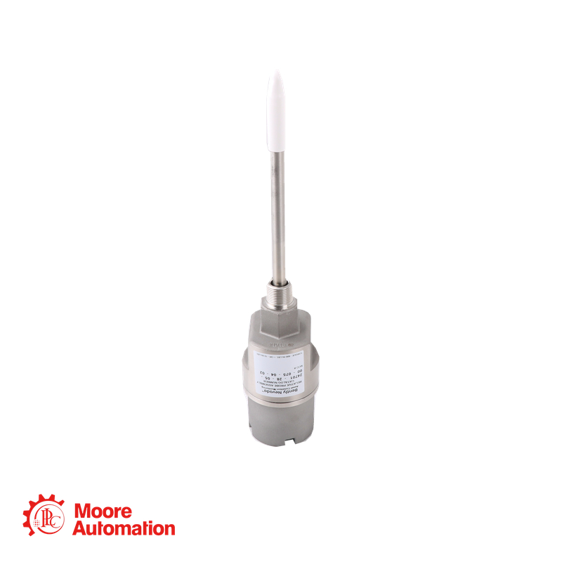
990-04-70-03-00
Two-wire 4–20 mA model for relative shaft-vibration measurement.
View exact product details
991-06-70-02-05
Two-wire 4–20 mA model for axial-position or thrust measurement.
View exact product details
990-10-50-03-00
Another Moore-listed 990 option for two-wire 4–20 mA vibration measurement.
View exact product details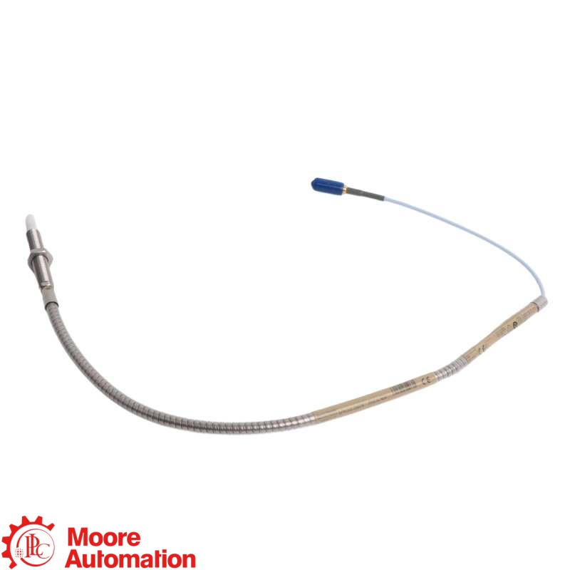
330910-00-07-05-02-05
A Moore-listed 3300 NSv proximity probe for related measurement-chain enquiries.
View exact product detailsSend the full nameplate before requesting a replacement.
Contact Frida for availability and quotation. Final fit and machinery-protection acceptance require the manufacturer documentation and your site’s verification procedure.


 Tell Us Your Needs !
 IPv6 network supported
|